Tag: Arab

  • Arab Press Register

    Arab Press Register

    In the Sum­mer of 2013 I set up a form to col­lect details of Arabs press­es around the world.  There are 19 press­es reg­is­tered at the moment run­ning in age from about 1892 to 1907.

    If you run an Arab and are will­ing to share the details, please com­plete the Arab Reg­is­ter.  In the com­ing months, I’ll organ­ise a way of shar­ing the con­tact details of Arab users.

    Ben

  • The Wipers Times

    The Wipers Times

    The BBC will broad­cast a pro­gramme detail­ing the Wipers Times, a trench mag­a­zine made by sol­diers at Ypres in World War I.  I under­stand Tim Hon­nor’s Arab will have star billing!

  • Taking an Arab Apart

    Taking an Arab Apart

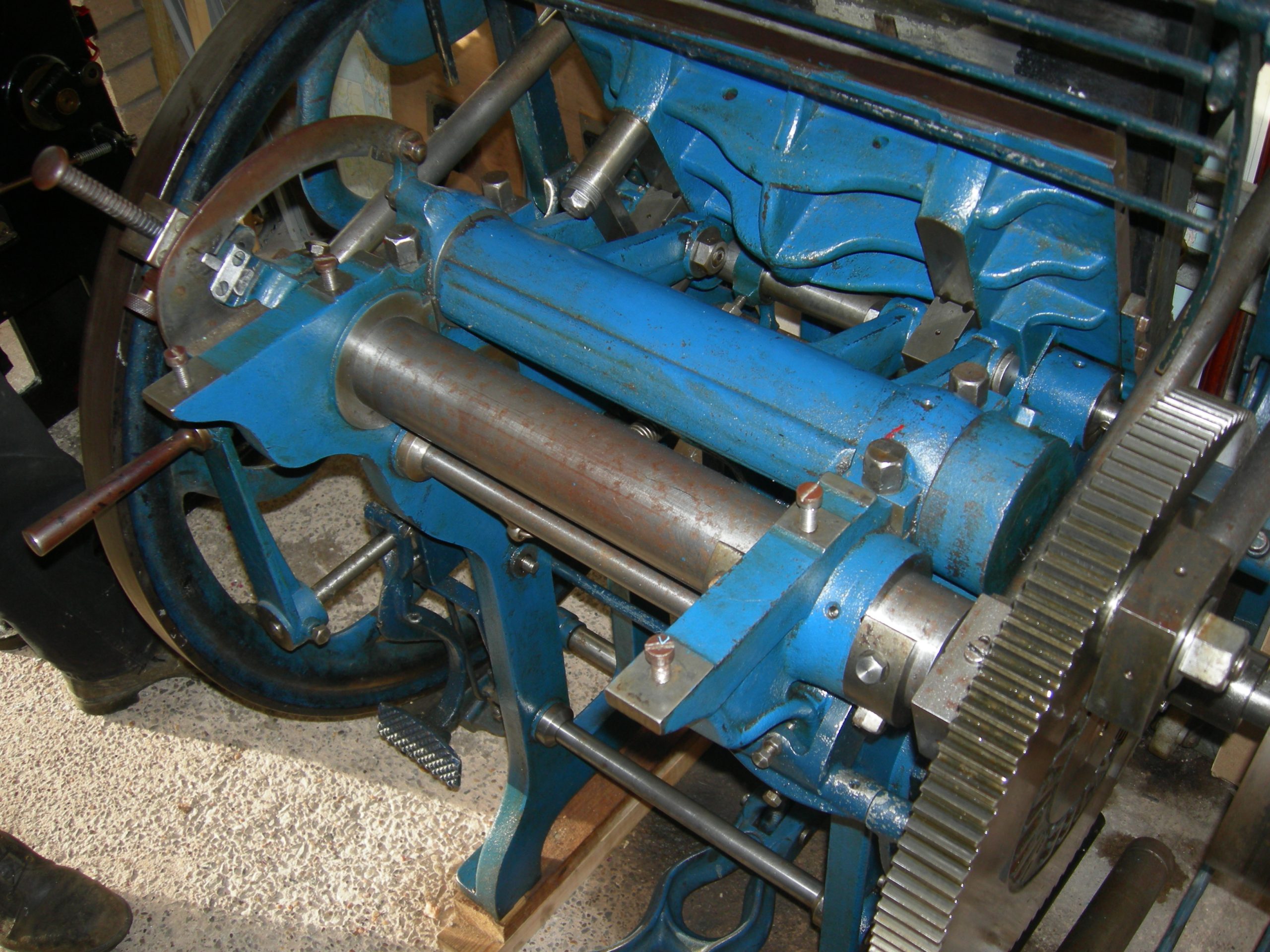
    This is an account of dis­man­tling a Crown Folio Arab Plat­en. The machine is ear­ly (Ser­i­al Num­ber 1086 c. 1892) but has had a num­ber of safe­ty fea­tures fit­ted. The guide below shows the major steps and will be added to. There’s a spe­cial sec­tion at the foot of this page about the brak­ing sys­tem.

    The main body of the Machine

    The start­ing point: a com­plete Arab

    Arab: com­plete machine with spare Arab Wheel” shown

    Ink­ing Disk Removed (remem­ber to replace the bolt under­neath).

    Arab: Ink­ing Disc Removed

    Feed board removed

    Arab: feed boards removed

    One of the ink­ing arms removed. Remem­ber that they are under the pres­sure of a spring so you have to keep hold of the arm as you release. In prepa­ra­tion for this you should have removed the rollers and stocks; and also removed the met­al bar which links left and right roller arms: keep this safe!

    Arab: ink­ing arms removed

    Over-arch­ing guard removed by unbolt­ing one site of the guard bars (not pic­tured)

    There are two strong springs which force the front plat­en towards to back plat­en. These need to be un-hooked while the front plat­en is almost ver­ti­cal. The two col­lars and hooks on the plat­en site need to be loos­ened so that the bar can be slid out lat­er on.

    Arab: Plat­en Springs Removed (look­ing from front to back under the machine)

    The two bolts on the left of the front plat­en must be removed so that the front plat­en is held only on the sup­port­ing bar. Remove the sup­port­ing bar and lift the front plat­en out. This is fair­ly del­i­cate as it will still con­tain the frisket motion.

    Arab: front plat­en removed

    The Arab wheel can now be slid from left to right and removed from the machine

    Arab wheel removed

    The rock horse’ is now removed. This is the U‑shaped met­al cast­ing which forces the front plat­en upwards. This rests in two slots is the frame cov­ered by two semi-cir­cu­lar cast­ings bolt­ed down.

    Arab: rock horse removed

    The back plat­en is now removed as a sin­gle large unit: includ­ing the plat­en and the sup­port­ing cast­ing. This is very heavy but will save trou­ble because the back plat­en will not have to be re-adjust­ed. The eccen­tric is also removed: this is the rod which holds the impres­sion lever.

    Arab: back plat­en removed

    The braking system

    Side view of the brak­ing sys­tem

    Arab: brak­ing sys­tem from side

    Top view of the brak­ing sys­tem

    Arab: top of brak­ing sys­tem
  • History of the Jobbing Platen

    History of the Jobbing Platen

    After the 1830s, the growth of the postal ser­vice and the expan­sion of com­merce led to growth in demand for small, print­ed arti­cles.  The Job­bing Plat­en met this need for the print­er: being quick­er than the ear­li­er hand press­es; and more suit­ed to small work than cylin­der press­es. It’s tempt­ing to think that the plat­en press sim­ply appeared — ful­ly formed — but there were many small advances that made that style of press pos­si­ble. Daniel Tread­well, an Amer­i­can, sought an 1818 patent to pro­tect his design for a mod­i­fied hand press that used foot pow­er (like a trea­dle) to deliv­er the impres­sion.  He trans­ferred the inven­tion to Eng­land and the firm of Baisler and Napi­er made the machine at their works at Lloyds Court, Crown Street, Soho; but only one is report­ed to have been sold.  The rotat­ing ink disc was invent­ed between 1819 and 1820 by Sir William Con­gereve for secu­ri­ty print­ing.  John Kitchen of New­cas­tle Upon Tyne patent­ed the ver­ti­cal forme in 1834.  It seems the machine would not have been com­mer­cial­ly suc­cess­ful, but was designed in the style of goth­ic church fur­ni­ture”.

    The First Usable Platen

    Stephen Rug­gles, from Boston USA, devel­oped the Engine press in 1839 but the bed and plat­en were hor­i­zon­tal.  Despite this, the press claimed 1,200 impres­sions per hour.  It was his devel­op­ment of 1851 of the Card and Bill­head Press” that opened the era of the first usable plat­en: this relied on his strange ink­ing mech­a­nism.  The approach is to have a large cylin­der, flat on one side for the type.  The cylin­der is cov­ered in ink and as the rollers pass around it, they draw ink from the cir­cu­lar part of the cylin­der and deposit it on the forme.  This press was made in Britain by the Birm­ing­ham Machin­ist Com­pa­ny as the Invic­tus and also Fur­ni­val and Com­pa­ny of Red­dish.  The prin­ci­ple was lat­er adapt­ed by Adana for their T/P48.

    The Modern Platen

    The pro­to­type plat­en press was devel­oped by George Gor­don of New York.  His ear­ly press (1851) was named The Alli­ga­tor because of its rep­u­ta­tion of crush­ing limbs of those feed­ing the press.  This first ver­sion had a fixed ink­ing pan­el, it was 1856 before he added the rotat­ing ink­ing disc.  In 1872, the throw off” was added: a mech­a­nism to allow the oper­a­tor to dis­able the impres­sion when a sheet had been mis-fed, for exam­ple.  Again, the idea was not new hav­ing been patent­ed in 1852 by James Young of Philadel­phia. Crop­per of Not­ting­ham began to make Gor­don’s press­es under the name Min­er­va, but the term Crop­per to define that type of press became com­mon­place.  Oth­er, local­ly designed, press­es used Gor­don’s idea like the Arab from Hal­i­fax.

    The Parallel Platen

    Improv­ing on the clam shell” approach, Mer­rit Gal­ly of New York devel­oped a press in 1859 called the Uni­ver­sal which brought the bed and the plat­en togeth­er with a par­al­lel impres­sion.  This was improved by the Vic­to­ria and Phoenix press­es.  In the UK, Green­wood and Bat­ley of Leeds sold a very sim­i­lar press under the name Sun; Daw­son’s of Otley the Mitre; and Har­rild of Lon­don the Fine Art Brem­n­er.

    The Powered, Automatically-Fed Platen

    Know­ing that the effort of a boy could not be sus­tained to thou­sands of impres­sions each hour, work began on mak­ing effi­cien­cies of space and pow­er.  In 1893, Har­rild of Lon­don cre­at­ed a plat­en press run­ning back-to-back: two mov­ing platens each print­ing against a sin­gle, two-sided, fixed bed. With steam and elec­tric pow­er, the next chal­lenge was to feed the press with paper. A grip­per was patent­ed by God­frey in the 1880s, and an auto­mat­ed feed for US Chan­dler and Price press­es was being sold by 1913.  Per­haps most known to us in the UK is the inven­tion of Gilke, a Hei­del­berg Engi­neer, who cre­at­ed the wind­mill feed in 1912 which was incor­po­rat­ed in to the 1925 Hei­del­berg Auto­mat­ic Plat­en.

  • Platen Presses

    Platen Presses

    Plat­en press­es here include press­es pow­ered by foot, steam or elec­tric­i­ty. Their main char­ac­ter­is­tic is that paper is fed into a jaw’ with the type on one side and paper on the oth­er. Some have auto­mat­ic feeds, so that paper does­n’t have to be sup­plied by hand for each impres­sion.

    These machines formed the main­stay of job­bing print­ers let­tr­press work up to the 1980s, and are used today by print­ers for cut­ting, creas­ing and num­ber­ing.

    [wpv-view id=“151752”]
  • Robert Smail’s, Innerleithen

    Robert Smail’s, Innerleithen

    Robert Smail’s Print­ing works — a prop­er­ty of the Nation­al Trust for Scot­land — is a time cap­sule of a long-estab­lished firm in the charm­ing Scot­tish bor­ders town of Inner­lei­then. The NTSs site shows infor­ma­tion about the print­ing works, along with open­ing times.

    Robert Smail’s Print­ing Works, 79 High Street, Inner­lei­then, Scot­tish Bor­ders, EH44 6HA
  • Bradford Industrial Museum

    Bradford Industrial Museum

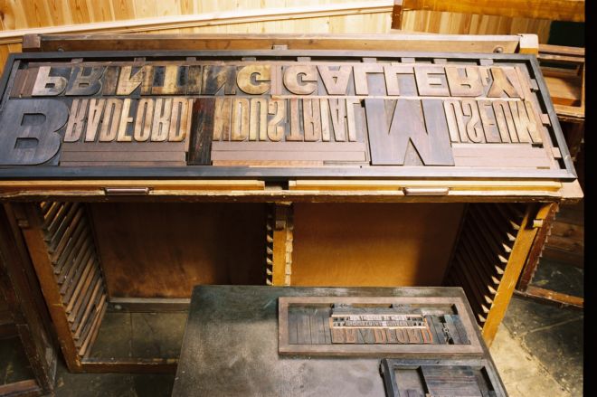
    Brad­ford Dis­trict Coun­cil’s Indus­tri­al Muse­um has a large area ded­i­cat­ed to print­ing, sup­port­ed by a band of enthu­si­as­tic vol­un­teers. Maps and open­ing hours are online, but a vis­it on Wednes­day after­noon is nor­mal­ly when there’s most activ­i­ty in the print­ing shop.

    Brad­ford Indus­tri­al Muse­um and Hors­es at Work, Moor­side Mills, Moor­side Road, Eccleshill, Brad­ford, BD2 3HP
  • Buying and Running an Arab

    Buying and Running an Arab

    The Arab is a mix of cast-iron frame; steel rods and brass. Machines were fet­ed for their reli­a­bil­i­ty and stur­di­ness. They have to be kept well-oiled and clean. When buy­ing, look out for –

    • cracks in the frame (dif­fi­cult to repair)
    • jud­der on open­ing the plat­en (could be a symp­tom of sig­nif­i­cant wear in the bear­ings)
    • any loose­ness of the plat­en: test by try­ing to pull the plat­en apart from the forme when closed up

    The machine body was paint­ed in Roy­al Blue’ but debate con­tin­ues about the exact shade, and whether dif­fer­ent shades were used. The brass roller arms were the only part of the machine to be paint­ed Pil­lar Box Red’. While the machine alone is great, also look out for –

    • man­u­als or erec­tion instruc­tions
    • addi­tion­al chas­es — the Arab came with full-size and but­ter­fly’ chas­es; or even this slant­ed chase
    • roller stocks and bear­ers (per­haps for a third roller)
    • spare parts

    Dismantling an Arab

    This is a rever­sal of the erec­tion instruc­tions and is based on expe­ri­ence. Remem­ber to keep parts togeth­er as far as pos­si­ble (eg replace nuts on bolt ends as soon as they are removed) and keep things in whole, com­plete ele­ments — like the brak­ing mech­a­nism — remove this as one unit.

    1. Ink­ing mech­a­nism
    2. Feed boards
    3. Tym­pan — by remov­ing the blan­ket rod and wire
    4. Forme Ink­ing Equip­ment
      1. Ink­ing roller bar, ink­ing rollers and run­ners
      2. Roller brass­es — care­ful of the springs
      3. Swinger bars which hold the
      4. Ink­ing disk and bear­er
      5. Ink disk pick lever
    5. Safe­ty Guard
    6. Arab Wheel should be loos­ened
    7. Spring and Plunger to hold the Chase on the back plat­en
    8. Con­nect­ing Rods
    9. Back Plat­en
      1. Low­er the back plat­en
      2. Remove the bolts from the foot of the back plat­en legs
    10. Fly­wheel — remove with nut (may have left-hand thread)
    11. Trea­dle and con­nect­ing rod
    12. Frisket mech­a­nism
      1. Strap Guide Rod
      2. Blan­ket and Frisket shafts
      3. Frisket springs
    13. Die Plate and Bush­es — this is the thing which holds the rock-horse against the plat­en
    14. Remove springs from the Plat­en Hooks
    15. Front plat­en — by remov­ing the rod, and col­lect­ing the plat­en hooks
    16. Remove the Arab wheel all togeth­er
    17. Impres­sion adjuster
    18. Eccen­tic shaft (con­nect­ed orig­i­nal­ly to the impres­sion adjuster)
    19. Rock horse
    20. Crank shaft — orig­i­nal­ly con­nect­ed to the fly­wheel
    21. Clutch and trip link
    22. Remove the bolts on the stays
    23. Take one side from the oth­er

    Re-Erecting the Arab

    You can start work on get­ting the machine back togeth­er by fol­low­ing the orig­i­nal instruc­tions that came with each machine.

    Documentation

    The orig­i­nal doc­u­ments that came with each Arab have been con­vert­ed to PDF files by Steve Fish­er and Ben Wein­er. The Arab Parts List should be used with the Erec­tion Instruc­tions